
RC is the time constant of the RC charging circuit. This is the step response of an RC circuit.

Rc Circuit Formula Derivation Using Calculus Rc Circuit Calculus Circuit
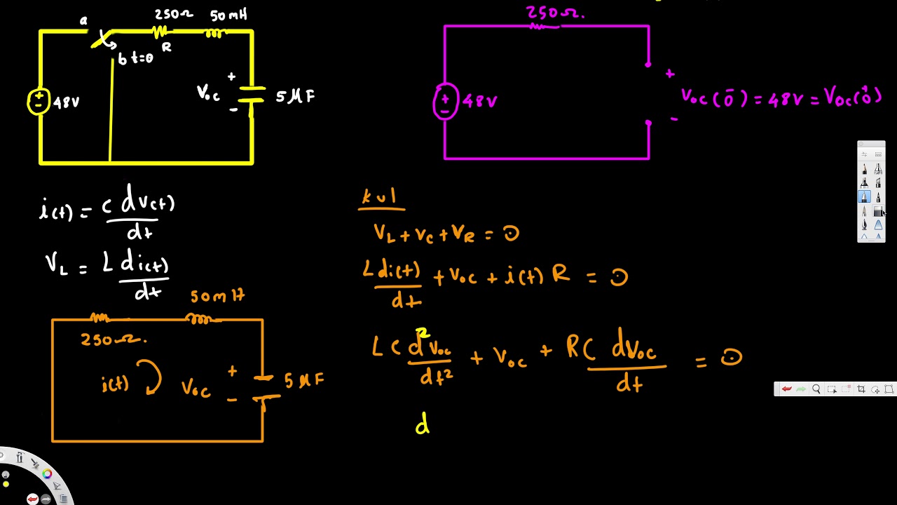
510a which can be replaced by the circuit in Fig.

. The time constant is measured in Tau τ. Find the initial conditions. Again we select the capacitor voltage as the.
Text RC RC step response is the most important analog circuit. Response of RL RC circuits. After five time constants 5τ the capacitor charge will reach 993.
The RC step response is a fundamental behavior of all digital circuits. Vs is the supply voltage. Find the equivalent circuit.
The time constant of any electronic circuit or system is mostly determined by the reactive components linked to it which can be capacitive or inductive. Step Response of Series RC Circuit Using Laplace Transform. 510b where Vs is a constant dc voltage source.
11 Differential Amplifier Circuits - 295 - and Vout2 2 V V out d out c 114 Let A V1 V out1 V in1 be the gain of differential amplifier due to input V in1 only and A V2 V out2V in2 due to input V in2 only. Figure 510 An RC circuit with voltage step input. The step response of a simple RC circuit illustrated in Figure 4 is an exponential signal with time constant τ RC.
Esides this timing parameter four other timing parameters are important in describing how fast or how slow an RC circuit responds to a step input. RC Step Response original article When something changes in a circuit the voltages and currents adjust to the new conditions. The 10-point is the point at which the output.
We use the method of natural plus forced response to solve the challenging non-homogeneous differential equation that models the. Esides this timing parameter four other timing parameters are important in describing how fast or how slow an RC circuit responds to a step input. These timing parameters are marked in Figure 4 at three voltage levels.
This delay is commonly referred to as the circuits time delay or Time Constant and it represents the circuits time response when a step voltage or signal is applied. Created by Willy McAllister. V tV_S V_0-V_Se -frac t RC Where V t is the voltage across the capacitor with respect to time V_S is the height of the step in supply voltage and V_0 is the initial voltage across the capacitor at t0.
In this example the pulse duration is half a second which is exactly five time constants. Learn more about step response of rc circuit using matlab. The step response of a simple RC circuit illustrated in Figure 3 is an exponential signal with time constant τ R.
T is the elapsed time since the application of the supply voltage. The 10-point is the point at which the output. The step response is the response of the circuit due to a sudden application of a dc voltage or current source.
The 10-point is the point at which the output. Besides this timing parameter four other timing parameters are important in describing how fast or how slow an RC circuit responds to a step input. An RC circuit responds to a step of voltage with a smooth transition between the starting and ending voltage.
Besides this timing parameter four other timing parameters are important in describing how fast or how slow an RC circuit responds to a step input. These timing parameters are marked in Figure 4 at three voltage levels. In analog systems it is the building block for filters and signal.
Text Rtext C RC step circuit. This step response happens billions of times every second inside digital devices. The 10-point is the point at which the output.
An electric circuit consisting of a resistance R and a capacitor C connected in series is shown in Figure-1. These timing parameters are marked in Figure 4 at three voltage levels. That means this is the most important analog circuit in.
This is the currently selected item. Given a voltage step at the input the time required to charge the capacitor to 632 of its full charge is known as the time constant τRC. To obtain the step response of the series RC circuit the applied input is given by.
Consider the RC circuit in Fig. These timing parameters are marked in Figure 3 at three voltage levels. Then from superposition theorem the output voltage V out is equal to V out A V1 Vin1 A V2 Vin2After substituting V in1 and V in2 from equation 111 and 112 the.
This video explains the approach to determine the response of an RC circuit when a DC source is suddenly applied across it. The step response of a simple RC circuit illustrated in Figure 4 is an exponential signal with time constant τ R. RC step response - derivation.
Vc is the voltage across the capacitor. The two examples can help the vie. After a period equivalent to 4 time constants 4T the capacitor in this RC charging circuit is said to be virtually fully charged as the.
The step response of a simple RC circuit illustrated in Figure 4 is an exponential signal with time constant τ RC. If the change is an abrupt step the response is called the step response. Consider the switch S is closed at mathrmmathittmathrm0.
E is an irrational number presented by Euler as. Step response of rc circuit. Through the equivalent inductor or initial.
But theres something in its derivation that I dont really agree with so Ill.

Rc Circuit Formula Derivation Using Calculus Rc Circuit Circuit Time Constant

Pid Controller Design Using Simulink Matlab Tutorial 3 Muhendislik Elektronik Teknoloji

Pin By Kritika Mishra On Exams Sheet Music Exam

Learn Melody Tone Generator Circuits Using Ht82207 Um3491 Mm5837 Eleccircuit Com Electronics Projects Circuit Projects Electronics Circuit
Rc Circuit Formula Derivation Using Calculus Time Constant Rc Circuit Product Rule

Inductor Capacitor Initial Conditions Step Response Of Rl Rc And Rlc Circuits Sinusoidal Steady State Response Ad E Book Circuit Electric Circuit

Linear Phase Response From 3 Way Eeweb Community Diagrama De Circuito Crossover Esquemas Eletronicos
Inverse Laplace Transform P12 36 Nilsson Riedel Electric Circuits 9e Sol Laplace Transform Laplace Circuit

Linear Phase Response From 3 Way Eeweb Community Diagrama De Circuito Crossover Esquemas Eletronicos

First Order And Second Order Passive Low Pass Filter Circuits Filters Circuit Passive

Build Your Own Microcontroller Based Pid Control Line Follower Robot Lfr Second Part Ermicroblog Microcontrollers Control Computer Technology

Quadcopter Pid Explained And Tuning Oscarliang Net Controlador Pid Sistema Electronico Sistema De Control

Inverting Amplifier Circuit High Pass Filters Amplifier

Circuit Diagram Symbols Lucidchart Circuit Diagram Electrical Symbols Electrical Wiring Diagram

Rc Circuit Formula Derivation Using Calculus Time Constant Rc Circuit Circuit

Rc Circuit Formula Derivation Using Calculus Rc Circuit Circuit High School Math

Rc Waveforms High Tech Gadgets Electronics Projects Electronics Illustration

Linear Phase Response From 3 Way Eeweb Community Diagrama De Circuito Crossover Esquemas Eletronicos

Pin On Computers Electronics Technology


